
DIY Catch Can
The Catch Can is a part of the system for collecting and recirculating the gases from the crank case and the cylinder head. When the engine is running there is some amount or air/fuel mixture escaping past the rings to the lower part of the engine. There it is mixed with oil , fuel and water vapors. If the crank case remains sealed the pressure inside will rise until it finds it way around any of the oil seals, usually blowing it off and causing oil leak. This caused a need for system that can get rid of the gases. In the beginning this system was just a hose connected to the crank case and tucked under that car, so everything can get away into the environment or on the pavement.
With the rising restriction related to emissions, different brands developed different ways to do it, but the basic principle is that the vapors are recirculated , burned and expelled with the exhaust. Depending on the state of the engine, the amount of vapors increase with the kilometers. This cause the intake tract to be covered in oil causing restriction and clogging tiny passage. This is very big problem, especially on the newer direct injection engines. This leads us to the catch can, which work is to accept the vapors, condense them(turn them back to liquid state), store them and release clean air back into the engine.
The Catch Can can be vented back to the engine or to the atmosphere. The second option is now very good, because you can’t ensure 100% cleaning effect in the can.
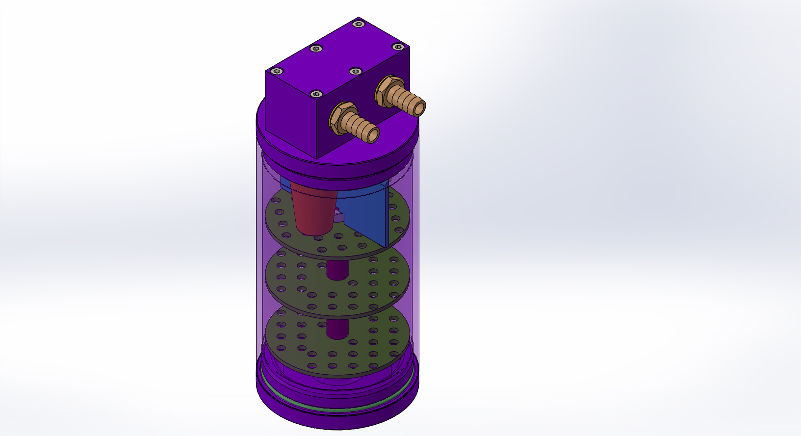
Below you see a picture of the setup and we are going to explain how it works. This is for turbo charged engines.

When the engine is turbocharged, you have two distinct operational states: as naturally aspirated and under pressure (boost).
When the engine is working as naturally aspirated(red contour), we have the one way valve(check valve) opened by the intake manifold vacuum, sucking the vapors from the crank case through the catch can, where they are being separated and the air continues to the engine.
When we have positive pressure (blue contour), the check valve is closed due to pressure in the intake manifold. The increased pressure cause more gases to pass around the rings pressurizing the crank case. The evacuation of the gases from there is supported by the low press area in front of the compressor inlet.
For naturally aspirated engine, you need, just the blue contour and you have to relocate the low pressure side to a place between the air filter and the throttle body.
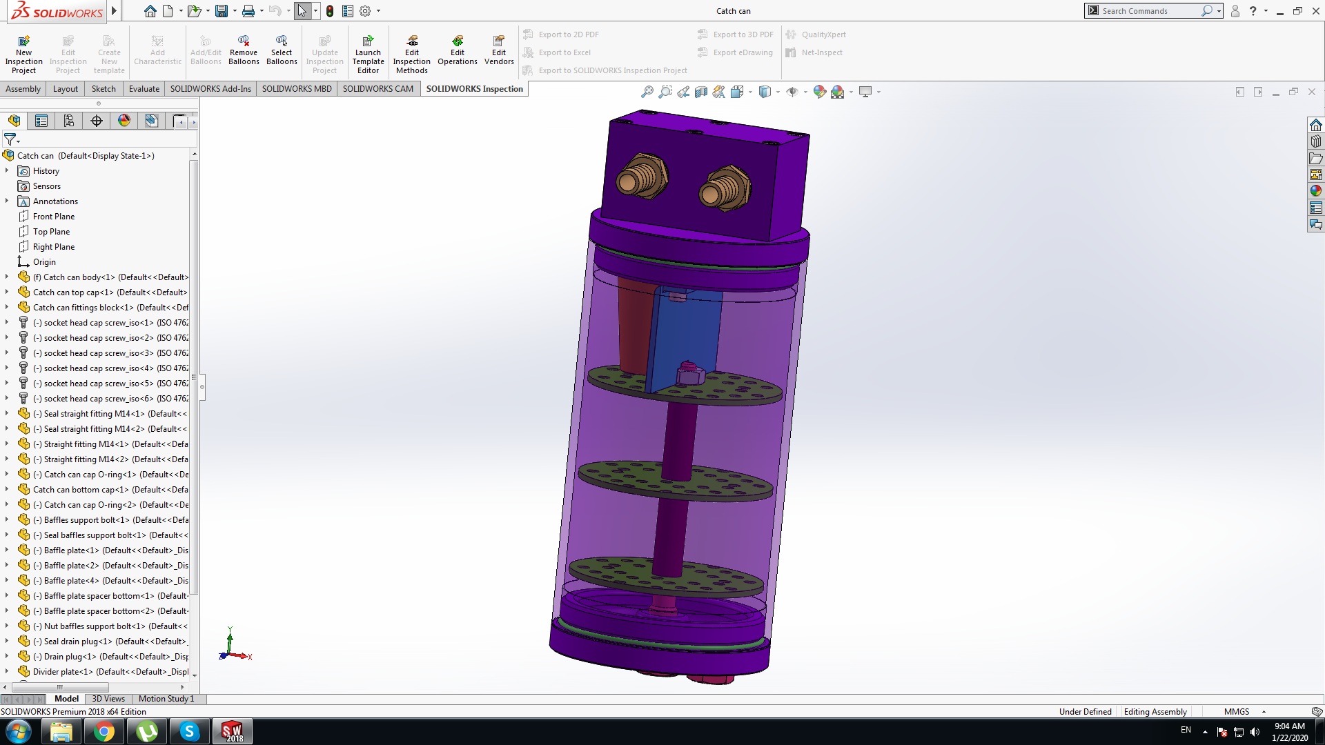
This model can give you a good idea who such an assembly is supposed to work and what the main parts and mechanism are.
You can always contact me with question or if you need help modifying the parts to your specifications.
This model is made by me and it is free for download and I want it to remain like that. The model cannot be used for commercial purposes.
If you undertake building this part, I can’t be held responsible for any injuries or damage to your property.
Catch Can
Catch Can system cut
Catch Can system cut
Catch Can exploded view
Catch Can system
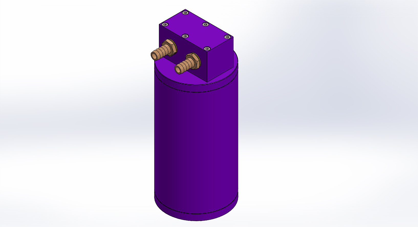
Catch Can
Catch Can
Catch Can
Here’s an interactive visual to show every detail. You can rotate and zoom in and out.
You can download the file in native SolidWorks part files and drawing or in several other file types like: