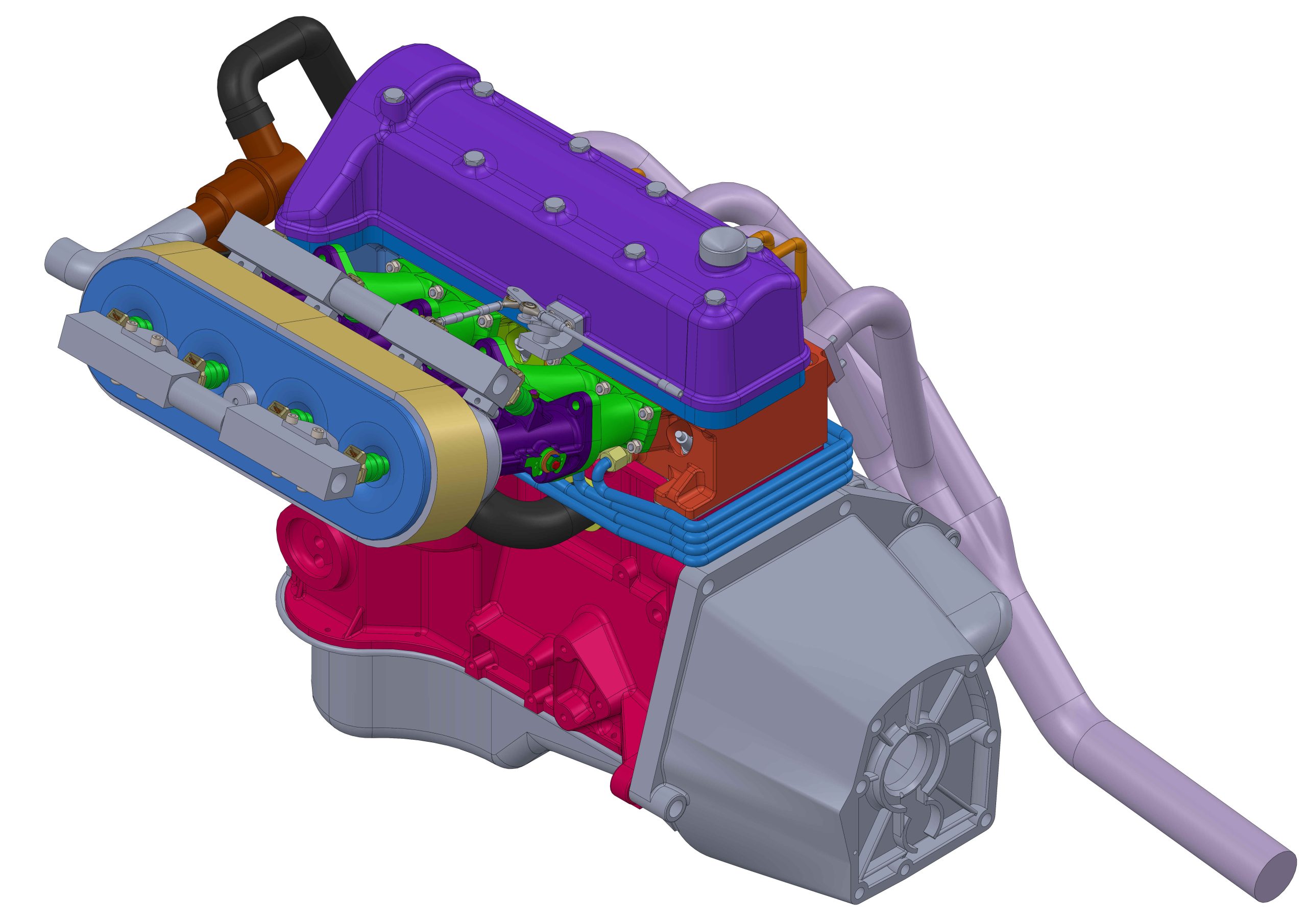
Lada(VAZ) 8 valve crossflow cylinder head
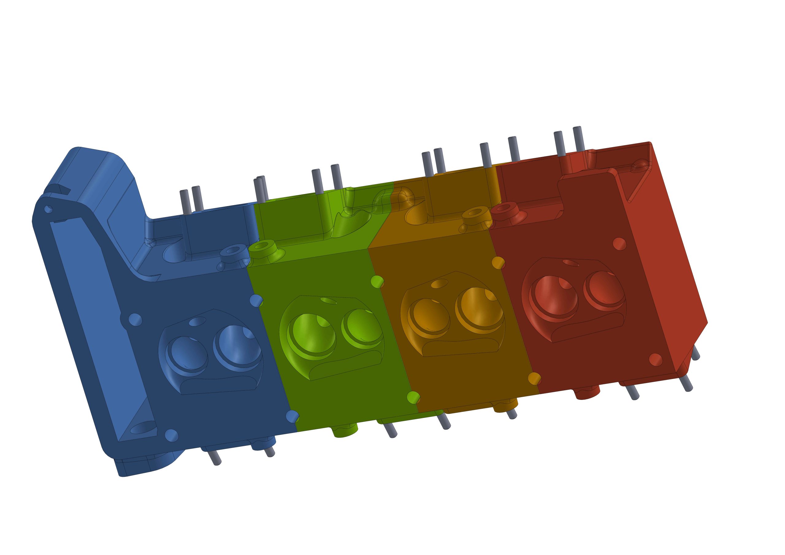
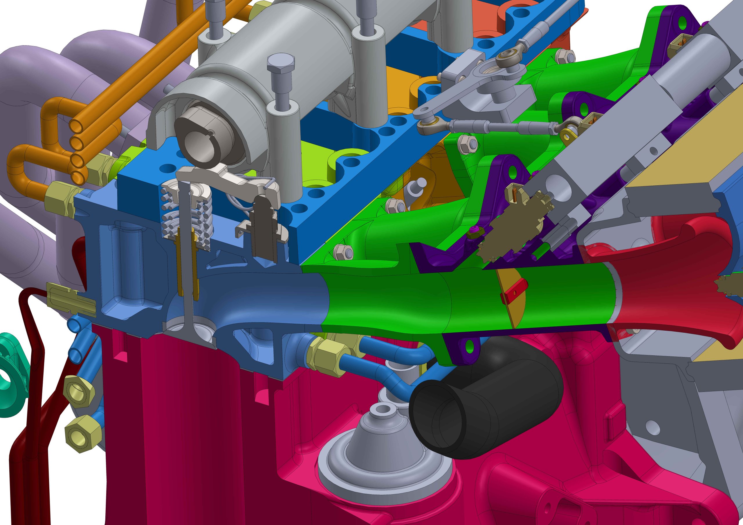
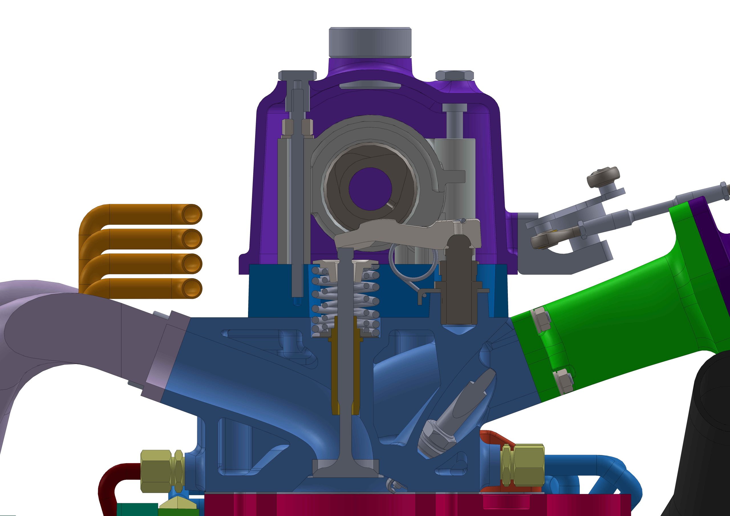
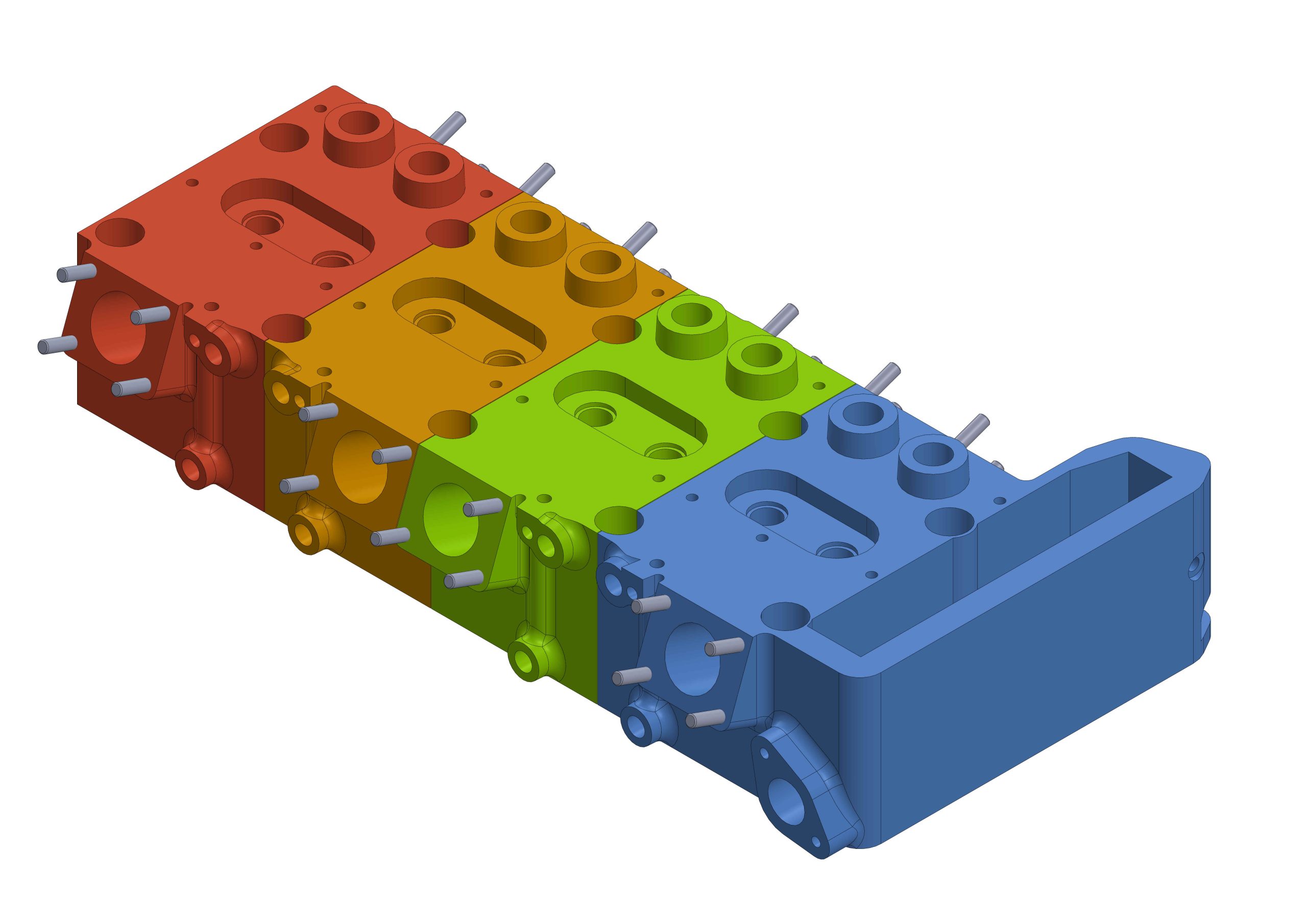
After I was few heads like this for other manufacturers, it came to me that this will be a good upgrade for all the classic Lada models. This also was checking one of my most important considerations, to use as much as possible stock parts. Buy the crossflow head and install all the parts from the old original VAZ cylinder head. Due to the small amount of aluminium that I can melt and pour, I decided to make the cylinder head in section. Basically, each cylinder have a separate cylinder head. Which on other hand caused another set of problems, related to cooling and draining the oil out of the heads. The head gasket will be solid and will close the combustion chamber. The oil and water will not pass through it. The oil will be drained from each cylinder head individually. The valley where the valve springs seat has a channel. This channel will be connected via fitting to a tubing that will drain the oil into the oil sump. The water part is a bit more complicated. The water will be driven into the engine by the water pump. Special adapter plate between the water pump housing and the engine block, will drive water to the drivers side of the cylinder head, where the cool water will get in. The water will go across the head to the top side on the passenger side and will get out and in the top of the radiator. The water for the engine block will get in from water pump side and will get out through a freeze plug on the driver side.
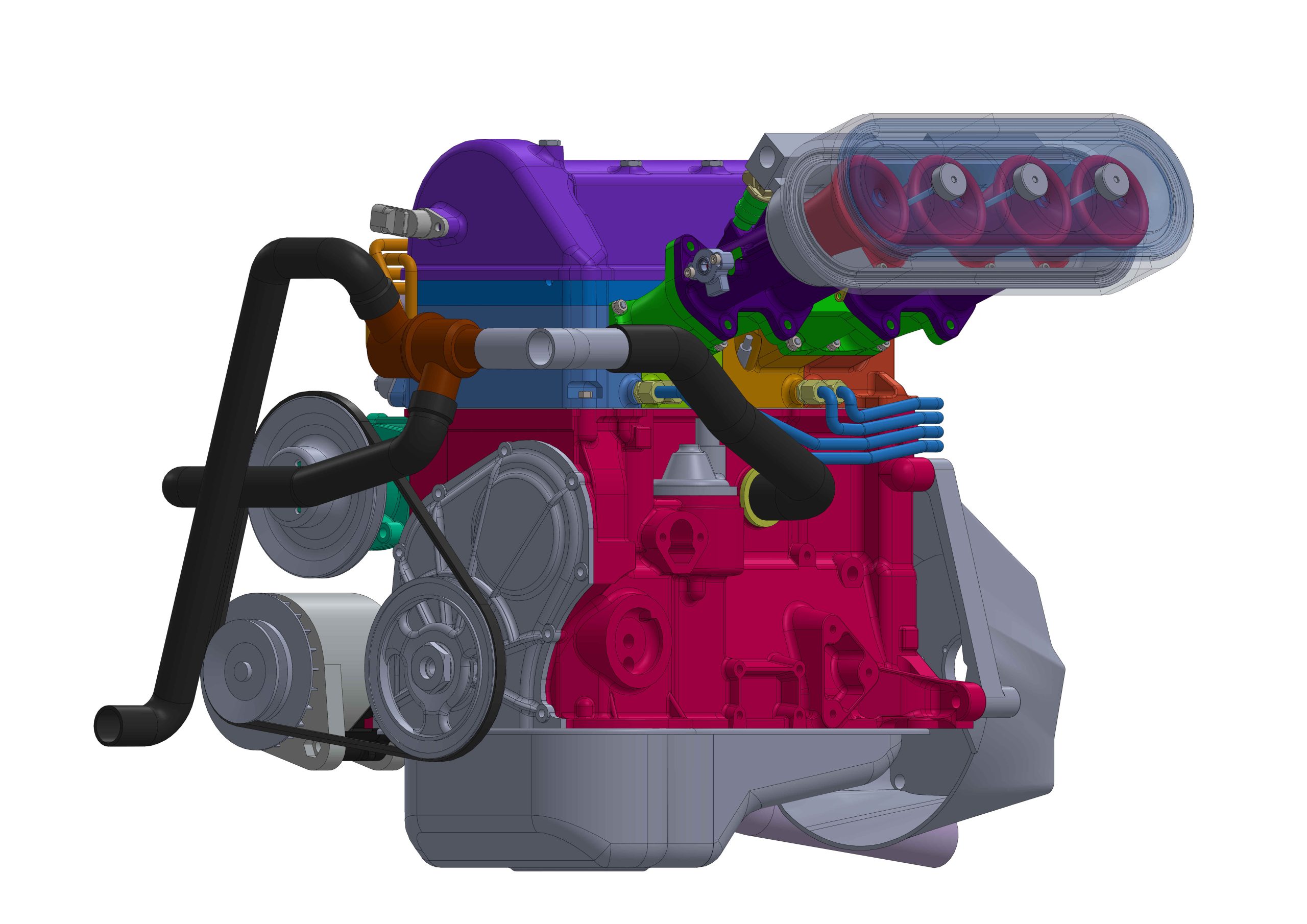
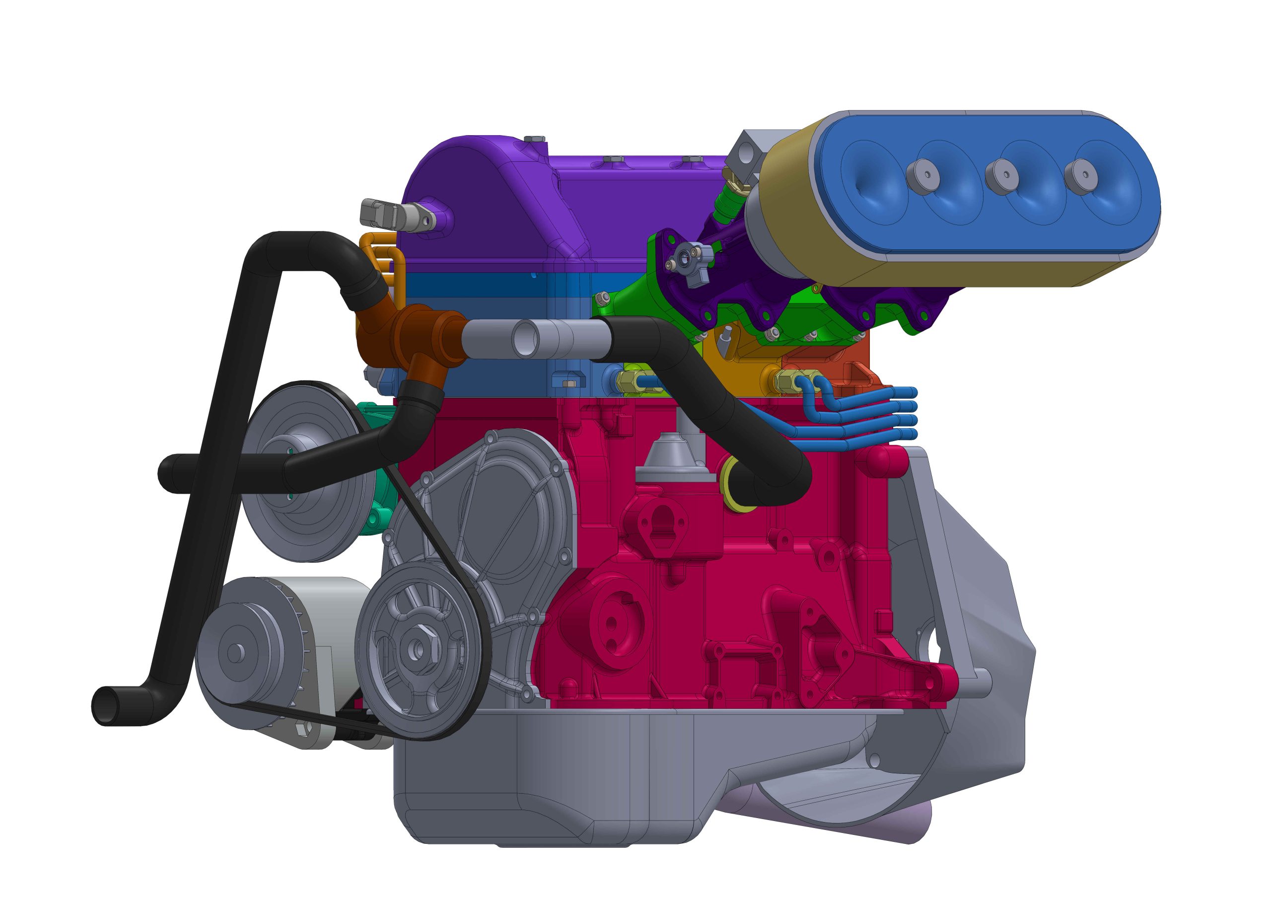
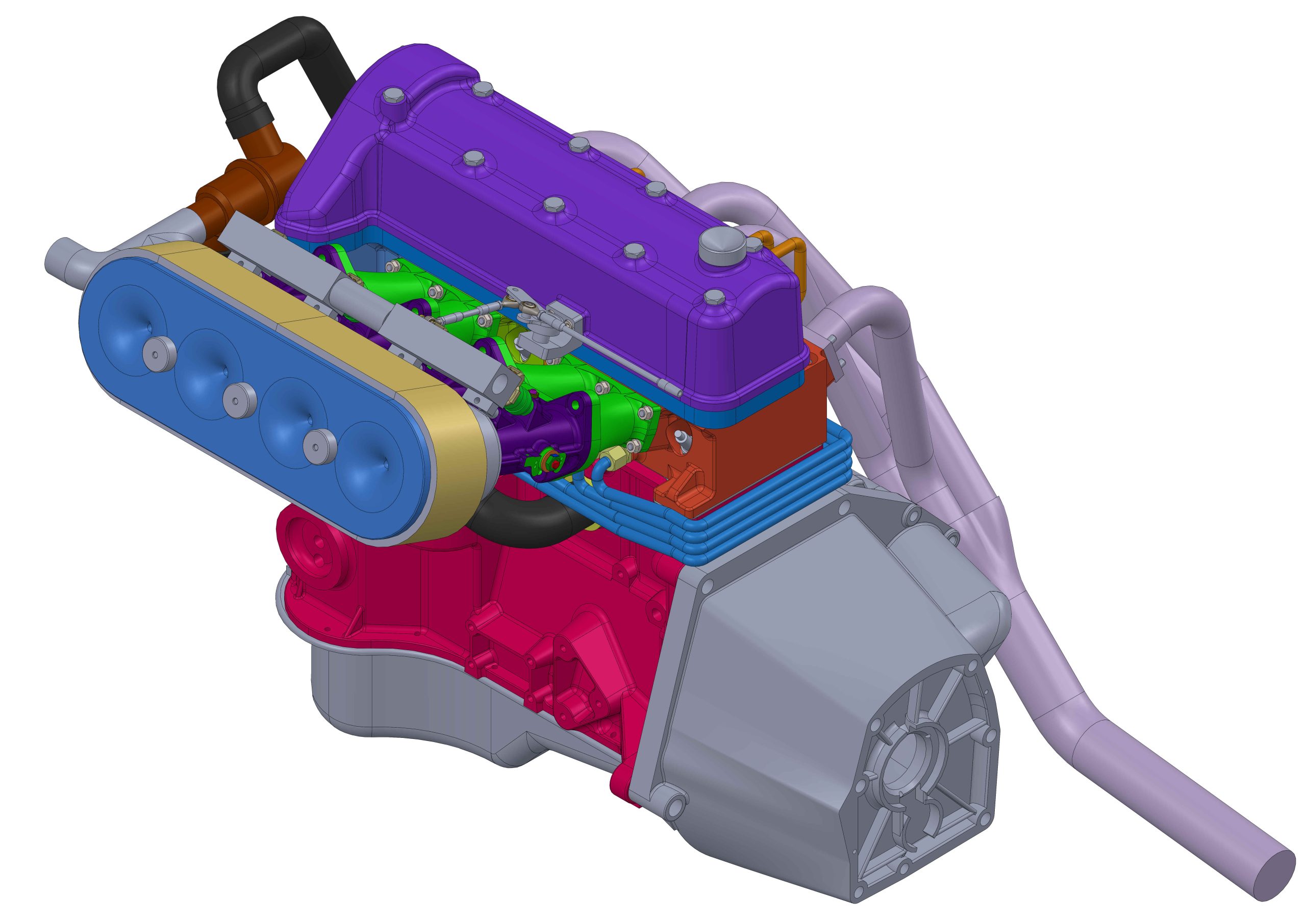
The 3D model shows a throttle bodies intake system(ITB), but this configuration will be very suitable for turbocharging as well. The intake system will undergo some changes. While I am preparing the patterns for casting, I will calculate the optimal lengths of the intake system and the position of the fuel injector. The top cover of the air filter is internally shaped, to assist the air getting into the air horns. The cover is also engineered to accept full set if fuel injectors. The idea here is, if the intake system gets too short, you will have a place to put the injectors.
The exhaust system here is for illustrational purposes. It also will be calculated and have two versions 4-2-3 and 4-1 preferably without having to cut the chassis to fit them.
Lada 8 valve crossflow cylinder head 1
Lada 8 valve crossflow cylinder head 2

Lada 8 valve crossflow cylinder head stage two injectors
Lada 8 valve crossflow cylinder head 4
Lada 8 valve crossflow cylinder head 5
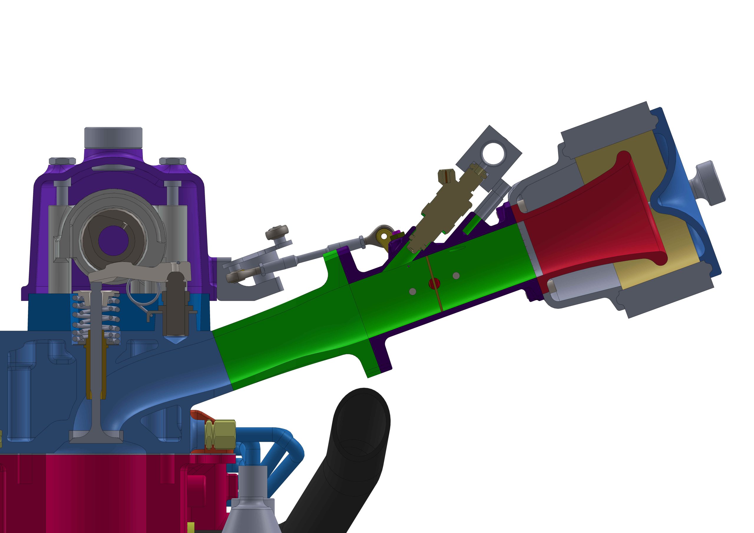
Lada 8 valve crossflow cylinder head intake system section
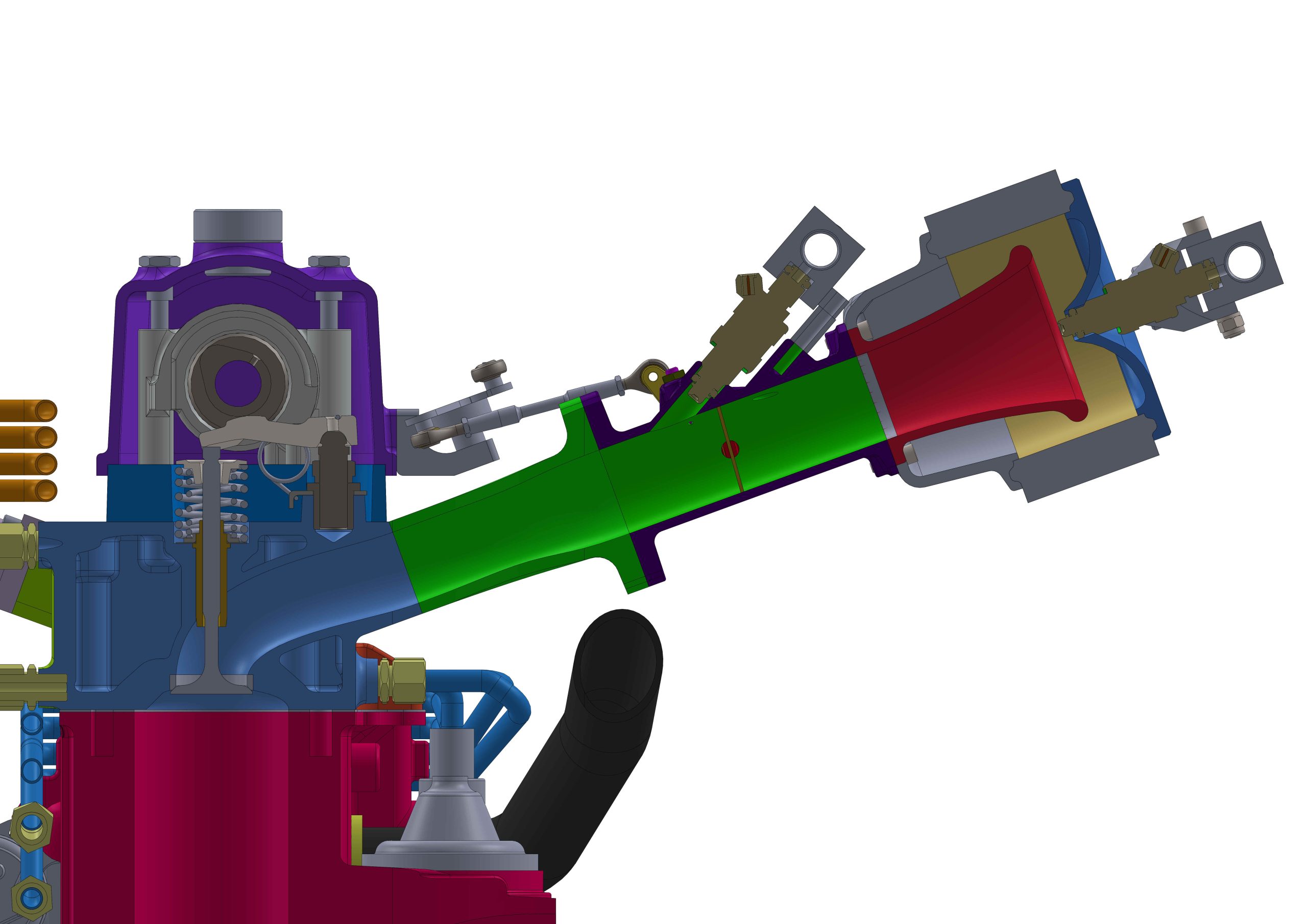
Lada 8 valve crossflow cylinder head intake system section with the second stage injectors
Lada 8 valve crossflow cylinder head section through intace valve and port, without the vavle cover
Lada 8 valve crossflow cylinder head section through the exhaust valve and port
Lada 8 valve crossflow cylinder head view from the exhaust side
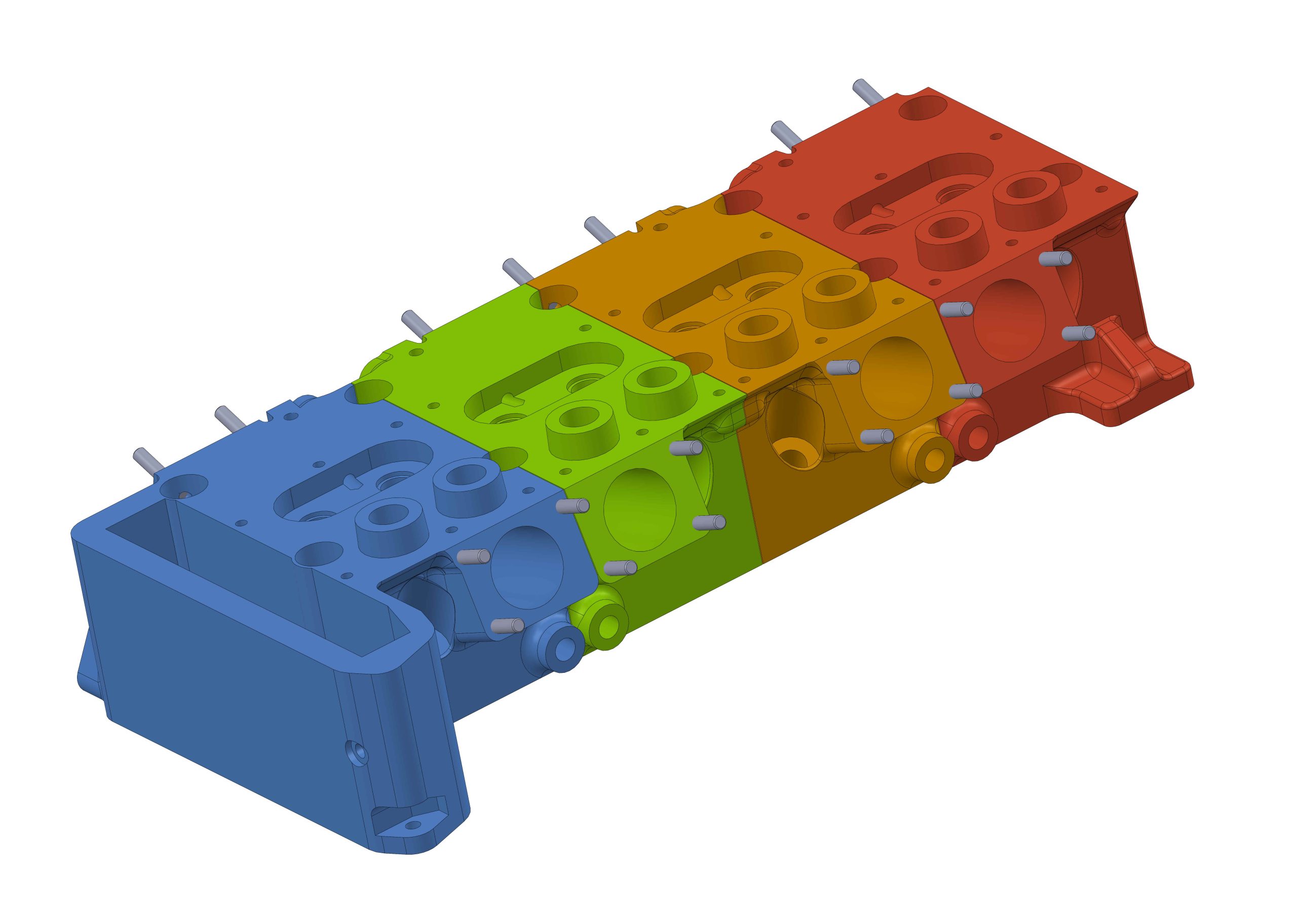
Lada 8 valve crossflow cylinder head view fron the intake side